March 24, 2013
There are a few projects that I will be covering in this blog, but the first I would like to document is one that I am currently building. It is a semi-automated vacuum forming machine that I use to create things like shaped lenses for automotive applications.
The requirements for the build are as follows.
- 12" x 12" table size
- Automated forming (vacuum on/off, heater on/off, timer set)
- Automated motion of mold (buck) being driven into the plastic
- Minimum custom parts
- Easy to assemble
- Easy to move
I have a preliminary design that was created in a CAD environment. I currently have all of the parts and am in the process of building the machine. I will document the build as I progress and be sure to post pictures and details. If the build proves successful, I would be happy to post a bill of materials for those who wish to recreate my machine.
Let's begin!
 |
| CAD rendering of preliminary design |
First thing I thought I would do is machine and drill the upper and middle stationary platforms. They are made from 1/2" thick MDF wood and I can easily work with this material with my CNC router (another project I will cover after this one).
I set up the tool paths and got to work cutting and drilling:
 |
| Machined Platforms |
As you can see, the real thing matches the model in the first post of mine. Take a look up closer and you can see the channel machined for the high temperature rubber seal. This will seal against the plastic to create an air tight chamber around the mold.
 |
| Channel for High-Temp Seal |
I also used MDF wood to make some spacers (10mm thick) for the bearing blocks that will hold the vertical ACME rod. While that was running, I was able to drill holes through my mitre gears for the roll pins that will secure them to the rods they attach to. I also had to drill out the centers of the miter gears to the 1/2" inner diameter because I will be using 1/2" rod.

 |
| Components cut and drilled |
So far so good! My strategy at this point is to prep as many items as I can before I begin assembling anything. That way the assembly process can be quick with few interruptions.
I managed to get a little more work done today. I put together my bearing blocks along with the wooden spacers. Also, I tapped the aluminum extrusions for the proper threads and proceeded to bolt a few things together. The CAD model gives me most of the dimensions I need, so everything should check out fine and fit up nicely.
 |
| Bearing blocks |
 |
| Main support posts fastened down |
 |
| Bearing blocks on supports |
As you can see in the last picture, the bearing blocks sit on the support extrusions. Carriage bolts slide through the slots and keep the bearing blocks in place. When I tighten them down, they will be spaced much farther apart to support the threaded rod while it rotates and lifts the platform with the mold.
Lastly, I was able to drill my nylon gears and the rods to accommodate the roll pins that keep them in place. I used an angle grinder to create flats on the threaded rod so it would be easier to start the drilling process without the bit walking. The picture below just shows the regular D profile rod.
 |
| Nylon miter gear mated to D rod |
Made some great progress today with the mechanical build. First, I started with setting up the shafts in the bearing blocks. The bearing blocks contain roller ball bearings that handle any radial loads. To handle axial loads, there are mini thrust bearings that get placed between thin washers.
 |
| Mini thrust bearings |
 |
| Thrust bearing and washer combination |
 |
| Shaft coupling |
 |
| Nylon miter gear |

Next I started setting up the D profile shaft. This side will have thrust bearings on both sides of the bearing block like so:

Then I put slid the vertical rods and bearing block assemblies back into the slotted channels. Lined things up on the bottom with the D shaft... and magically the right side miter gears line up perfectly:

I still have to drill the holes for those bottom bearing blocks, and set up the left side miter gear on the D shaft. I'll take care of that tomorrow!
March 29, 2013
Got a lot done today! Let's start with the heater box..
The heating box is the panel on top of the machine that produces the heat necessary to soften the plastic sheets. The goal here is to output uniform heat across the entire sheet of plastic. I found these great ceramic infrared panels online. They operate at 120V and are rated at 500W each. Conveniently, three of them together roughly covers 1 square foot of area. Therefore, I needed to build a housing to hold them. Sheet metal is easy to work with and cheap to laser cut. So I had some shapes cut that I just needed to weld together. The first geometry is just the outer walls of the box:
Then the heating panels were inserted into their mounting slots and placed in the box. The tabs were welded to locate this panel:
Here you can see the welded box with the heating elements removed:

Then I put slid the vertical rods and bearing block assemblies back into the slotted channels. Lined things up on the bottom with the D shaft... and magically the right side miter gears line up perfectly:

March 29, 2013
Got a lot done today! Let's start with the heater box..
The heating box is the panel on top of the machine that produces the heat necessary to soften the plastic sheets. The goal here is to output uniform heat across the entire sheet of plastic. I found these great ceramic infrared panels online. They operate at 120V and are rated at 500W each. Conveniently, three of them together roughly covers 1 square foot of area. Therefore, I needed to build a housing to hold them. Sheet metal is easy to work with and cheap to laser cut. So I had some shapes cut that I just needed to weld together. The first geometry is just the outer walls of the box:
 |
| Outer walls of the heating panel |
 |
| Created with simple bends and welds |
 |
| Top side of heater panel |
 |
| Tabs for welding |
Here you can see the welded box with the heating elements removed:
 |
| Top side |
 |
| Bottom side (without ceramic elements) |
 |
| Top panel on |
Ceramic elements were placed back inside. There will be a layer of ceramic fiber insulation that goes on top.
 |
| Ceramic infrared heating elements |
 |
| Heating elements back in without insulation |
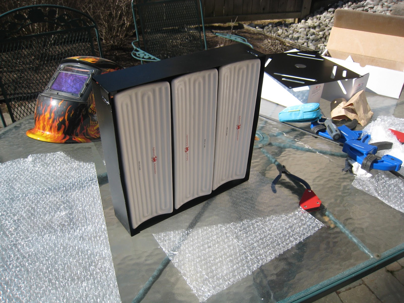 |
| Business side of the heating panel |


Next up is the platform that holds the mold, as well as the top board where the plastic is clamped into place. Hopefully finish some of that tomorrow! Enjoy your long weekend everyone!
Then I fastened down the hinge and clamp with some ABS plastic in place:
A final overview of the top platform.


Still lots more to do... but the mechanical build has been going great so far. Haven't had to do anything drastically different than what I had planned in CAD. We'll see how far all of this goes!
April 02, 2013
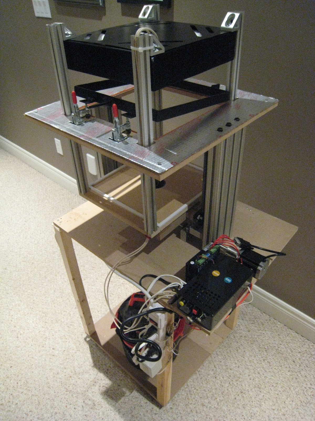
Things have been busy but I was able to mount the top platform and build the base. I wanted to get this done asap so I could conveniently work on the rest of this thing as it stands on it's own. It doesn't take up valuable work bench space anymore, and when it comes time to wire it, I can just sit in a chair beside it.
I put small 2" castor wheels on the bottom so I can just roll it around if it's in the way. It will also be necessary to roll it out of the room while I cut wood on my CNC machine. It kicks up a lot of wood dust and I don't want any of that around the heating elements.
Check out the pictures! You can also see the little shop vacuum I have on the platform at the bottom. Surprisingly this little unit provides enough vacuum for vacuum forming plastic up to 1/8" (3.165mm) thick. I haven't tried anything thicker but it's sufficient as long as you have a good seal.


I still need to mount the heater box and build the moving platform that holds the mold. Not much left to do mechanically!
The electronics should be fun! I love playing with Arduino!
April 04, 2013
For a change of pace I decided to start on the electrical aspect of this build. It is pretty simple and uses components that are easy to work with. The brains behind the operation is the Arduino Uno and I can easily write the code to make it control the stepper motor and the relays. The relay board is from .NET Gadgeteer and has four relays rated at 120V AC and 15A each. Perfect for turning my heater box and vacuum on/off and can be controlled by the Arduino.
There are also a few other electrical components that I added. Obviously I needed buttons and knobs as an interface with the machine. The buttons will be for (Start), (Platform Up), (Platform Down), while the knobs will control heating time and temperature. The temperature control knob is actually a 120V SCR electronic motor speed controller rated at 3000W. Basically it will just limit the amount of power available to the heaters and limit their temperature if necessary.
Let's take a look at the basic layout that I have set up. Everything will be contained in a generic black plastic project box:
I have a wiring schematic laid out in my head. In the coming days I'll put it on paper and then physically wire it up. I also have a pretty good idea of what I'm going to do with the code. Getting there!
April 11, 2013
It's been a few days but I managed to make progress. Unfortunately I've been busy with a bunch of other projects on the go (mostly my car), but something is better than nothing!
I finished up about 90% of the wiring. There are a few connections missing, such as from Arduino to the stepper motor driver, but that should take just 5 minutes. It isn't the cleanest wiring job, however, it allows me to easily disconnect wires if something is incorrect. I can always route the wires nicely once everything is finalized.
I also managed to finish up the heater box. All that was left to do was put the ceramic fiber insulation in the top, as well as wire in the ceramic terminal blocks. As you can see, heat resistant wire was also used in the heater box. I wouldn't want any of this stuff to melt!
Then I bolted the top down with the aluminum mounting brackets. These will mount to the vertical aluminum extrusions using the T-slots and suspend the heater above the top platform.
Lastly, I mounted the power bar to one of the front legs of the base. Gives quick and easy access to power supply, and the main switch to shut everything down if there is a problem.
There are a few more odds and ends to tie up before I can call this project complete. I've also started working on the programming code to make it all run. It's very straightforward and the logic is simple.
I think I will finish all of the wiring before I move onto anything else. I really want to test out the electronics and confirm everything works!
April 18, 2013
Things have been slow lately. Unfortunately I injured my leg and it's really kept me away from my projects. However, I'm beginning to feel a little better and I had some time to work on the machine today.
I was able to mount the control box, the 48V power supply for the step driver/stepper, and get the machine 99% wired. Many of the wires still need to be routed in a more organized fashion, but the main thing is to get it operational first. Check out some pictures below!
That's it for now. Going to get the motor turning tomorrow and I'll shoot some video! Check back again soon!
April 24, 2013
As promised, here is a quick video describing the controls and a demo of the electronics working together!
Almost done!
April 28, 2013
Finished up the build this weekend. Very excited to have the machine complete and I will be testing it this week (dialing in the heating time cycle and heat levels).
The last steps of the build were to build the mold platform, attach the heater, and connect the wires for the heating elements.
The mold platform is fairly simple. A flat piece of 1/2" MDF cut to size with a circular hole in the middle for the vacuum port. The vacuum port was purchased at Home Depot and you can find them at most home renovation stores. There are some pieces of drilled MDF on the side that are glued to the bottom of the platform. These attach to the acme nuts with 5/16" bolts. The vacuum hose attaches to the bottom of the vacuum port and I taped it to ensure an air tight seal.
In the following pictures, you will also notice a foam seal on top of the platform to seal against the bottom of clamping platform.
The heating panel is fastened to the mold platform so that they move together when the motor is activated. Also note that the heating box is attached to the T-slot on the aluminum bars. This will allow me to adjust the height of the heating element from the plastic when I set up the machine.
The wires for the heating element were also hooked up and the lid on the control box was fastened down. This is what it looks like for now:
Lastly, a few overall shots of the machine as it stands. I will be sure to take some video of the test runs and post up the successful ones. I can't wait to make some vacuum pulls!
Check back soon to see it working!
May 12, 2013
It has been a busy couple of weeks but I've finally gotten around to making a video of the machine working. I've included an explanation of all of the components for those who have not been following the build on this blog.
Unfortunately I still haven't tested any plastic but I have everything working as planned.
The only problem I've run into so far is that I bought the wrong stepper driver for my stepper motor. I assumed that it would single step along with the microstepping that was advertised but it does not single step. I am stuck running at 1/4 steps in the meantime but I have another driver on order. In the video below, the mold platform is therefore only moving at 1/4 speed.
Enjoy the demonstration and please leave a comment if you have any questions!
Next up, testing!
March 30, 2013
Another productive day today. Unfortunately I didn't have the chance to snap too many pictures during the whole build process. However, I captured the important details.
The items below are the clamp and the hinge that the clamp rotates about. They're made from 1/8" thick flat stock steel just cut, welded, drilled. Finished with some high heat bbq/stove paint:
Then I started cutting up some heat shield material. You can find this stuff at Home Depot. I believe it is made for furnaces, but it's easy to cut and works great. I just wanted to prevent the wood from getting too hot with the heating box sitting right above it.
Another productive day today. Unfortunately I didn't have the chance to snap too many pictures during the whole build process. However, I captured the important details.
The items below are the clamp and the hinge that the clamp rotates about. They're made from 1/8" thick flat stock steel just cut, welded, drilled. Finished with some high heat bbq/stove paint:
 |
| Clamp and hinge |
 |
| Heat shield |
 |
| Back side |
Added the toggle clamps (that clamp down on the steel tabs):
Cut and adhered the high temperature seal in it's groove. This seals against the bottom side of the plastic. The pressure from the clamp creates the air tight seal:
 |
| Toggle clamps |
Cut and adhered the high temperature seal in it's groove. This seals against the bottom side of the plastic. The pressure from the clamp creates the air tight seal:
 |
| High temperature seal |


Still lots more to do... but the mechanical build has been going great so far. Haven't had to do anything drastically different than what I had planned in CAD. We'll see how far all of this goes!
April 02, 2013
Things have been busy but I was able to mount the top platform and build the base. I wanted to get this done asap so I could conveniently work on the rest of this thing as it stands on it's own. It doesn't take up valuable work bench space anymore, and when it comes time to wire it, I can just sit in a chair beside it.
I put small 2" castor wheels on the bottom so I can just roll it around if it's in the way. It will also be necessary to roll it out of the room while I cut wood on my CNC machine. It kicks up a lot of wood dust and I don't want any of that around the heating elements.
Check out the pictures! You can also see the little shop vacuum I have on the platform at the bottom. Surprisingly this little unit provides enough vacuum for vacuum forming plastic up to 1/8" (3.165mm) thick. I haven't tried anything thicker but it's sufficient as long as you have a good seal.


I still need to mount the heater box and build the moving platform that holds the mold. Not much left to do mechanically!
The electronics should be fun! I love playing with Arduino!
April 04, 2013
For a change of pace I decided to start on the electrical aspect of this build. It is pretty simple and uses components that are easy to work with. The brains behind the operation is the Arduino Uno and I can easily write the code to make it control the stepper motor and the relays. The relay board is from .NET Gadgeteer and has four relays rated at 120V AC and 15A each. Perfect for turning my heater box and vacuum on/off and can be controlled by the Arduino.
There are also a few other electrical components that I added. Obviously I needed buttons and knobs as an interface with the machine. The buttons will be for (Start), (Platform Up), (Platform Down), while the knobs will control heating time and temperature. The temperature control knob is actually a 120V SCR electronic motor speed controller rated at 3000W. Basically it will just limit the amount of power available to the heaters and limit their temperature if necessary.
Let's take a look at the basic layout that I have set up. Everything will be contained in a generic black plastic project box:
 |
| User interface |
 |
| Basic Layout |
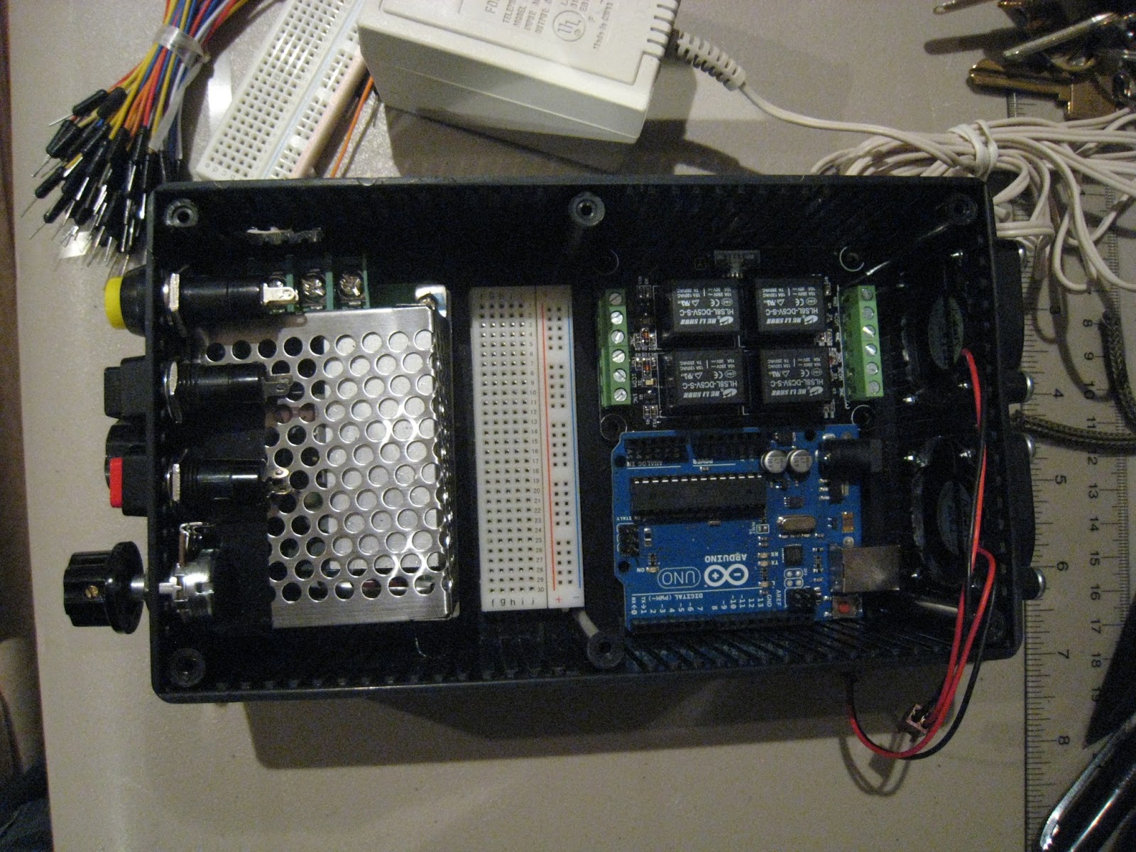 |
| Arduino fun! |
I have a wiring schematic laid out in my head. In the coming days I'll put it on paper and then physically wire it up. I also have a pretty good idea of what I'm going to do with the code. Getting there!
April 11, 2013
It's been a few days but I managed to make progress. Unfortunately I've been busy with a bunch of other projects on the go (mostly my car), but something is better than nothing!
I finished up about 90% of the wiring. There are a few connections missing, such as from Arduino to the stepper motor driver, but that should take just 5 minutes. It isn't the cleanest wiring job, however, it allows me to easily disconnect wires if something is incorrect. I can always route the wires nicely once everything is finalized.
 |
| Wiring |
 |
| Arduino stickers fit nicely on the fans! |
 |
| A few more wires to go... |
 |
| Ceramic fiber insulation and ceramic terminal blocks |
 |
| Heat resistant wire |
 |
| Aluminum mounting brackets |
 |
| Main power supply |
I think I will finish all of the wiring before I move onto anything else. I really want to test out the electronics and confirm everything works!
April 18, 2013
Things have been slow lately. Unfortunately I injured my leg and it's really kept me away from my projects. However, I'm beginning to feel a little better and I had some time to work on the machine today.
I was able to mount the control box, the 48V power supply for the step driver/stepper, and get the machine 99% wired. Many of the wires still need to be routed in a more organized fashion, but the main thing is to get it operational first. Check out some pictures below!
 |
| Control Box + Step Driver |
 |
| Overview |
 |
| 48V Power Supply |
April 24, 2013
As promised, here is a quick video describing the controls and a demo of the electronics working together!
April 28, 2013
Finished up the build this weekend. Very excited to have the machine complete and I will be testing it this week (dialing in the heating time cycle and heat levels).
The last steps of the build were to build the mold platform, attach the heater, and connect the wires for the heating elements.
The mold platform is fairly simple. A flat piece of 1/2" MDF cut to size with a circular hole in the middle for the vacuum port. The vacuum port was purchased at Home Depot and you can find them at most home renovation stores. There are some pieces of drilled MDF on the side that are glued to the bottom of the platform. These attach to the acme nuts with 5/16" bolts. The vacuum hose attaches to the bottom of the vacuum port and I taped it to ensure an air tight seal.
In the following pictures, you will also notice a foam seal on top of the platform to seal against the bottom of clamping platform.
 |
| Vacuum Port |
 |
| Foam Seal |
 |
| Heating Element Installed |
 |
| Salamander Heating Elements |
 |
| Finished Control Box |
 |
| Complete! |
 |
| Finished! |
May 12, 2013
It has been a busy couple of weeks but I've finally gotten around to making a video of the machine working. I've included an explanation of all of the components for those who have not been following the build on this blog.
Unfortunately I still haven't tested any plastic but I have everything working as planned.
The only problem I've run into so far is that I bought the wrong stepper driver for my stepper motor. I assumed that it would single step along with the microstepping that was advertised but it does not single step. I am stuck running at 1/4 steps in the meantime but I have another driver on order. In the video below, the mold platform is therefore only moving at 1/4 speed.
Enjoy the demonstration and please leave a comment if you have any questions!
Next up, testing!
Hi Chris,
ReplyDeleteI am currently working on a project that would require the heating of a ceramic element through the use of arduino uno. Would it be possible for you to post the code for regulating the ceramic heater, and perhaps a diagram if possible?
Thanks